The design
This first charm is intended to represent Kathy May’s time training at the Massachusetts General Hospital, which is the original and largest teaching hospital of Harvard Medical School. The design of the charm is inspired by the logo of MGH as well as that of Harvard. Because of the small size of the charm and the physical limitations of the 3D printing process, the details of the logos had to be stylized somewhat, but not too much that the logos were no longer recognizable. I also wanted to take advantage of having the third dimension to work with and make the charm more than just an extruded 2D shape. I thus took the graphical part of the logo, which represents the Ether Dome of the Bullfinch building, modeled it in 3D, and put it on the top of the charm like a roof. The Ether Dome is an architectural landmark on the MGH campus, but is also historically significant as the location of the first successful demonstration of surgical anesthesia in 1846. Before this, all surgery was done fully awake, if you can even imagine what that would have been like! Watch the video below for a look at the design and preparation stage of the creation of this charm:
Creating the 3D model
A digital 3D model of an object is needed to instruct the 3D printer how to make the object. I used Autodesk’s 123D Design to create the model. This program was free but unfortunately has been discontinued by Autodesk in favour of its other 3D modeling programs, TinkerCAD and Fusion 360, which are both free for personal use. The basic principles of the programs should be similar, though. 123D Design has a point-and-click interface that has a live rendering of the model, and it accepts keyboard input for more precise measurements. You start with primitive solids such as cubes and cylinders as well as with 2D shapes such as curves and text that are extruded or otherwise made into 3D solids. These are then combined and subtracted to create the final, complex model. The 2D drawing and text tools are adequate for many things but it’s also possible to import SVG (Scalable Vector Graphic) files from more sophisticated software such as Adobe Illustrator or the free/open-source Inkscape.
For this charm I used Illustrator to extract the shape of the shield from a file of the MGH logo. I also prepared the text with Illustrator to make use of fonts and typography tools not available in 123D Design. These were saved as SVG files and imported into 123D Design. There is a problem with small SVG files being distorted when imported (it may be some kind of rounding bug) so to get around it, create the file with larger dimensions and scale it back down after importing. I transformed these 2D images plus some simple 2D shapes drawn directly in 123D Design into the model of the charm using the extrude, shell, revolve, combine, and align tools. For a necklace charm, it is also important to position the opening for the chain so that the charm is weighted properly to stay upright when worn. To do this, I divided the charm into a top and bottom half, and measured the volume of the halves to ensure that the bottom half will be heavier than the top. Finally, I engraved some simple lettering into the inside of the charm. Watch the video below to see how I created the 3D model in 123D Design. The screen capture runs at 4x speed to save time:
This is a longer, more detailed version where the screen capture runs at 1x speed if you are interested in learning the process step by step (note: the video runs about 30 minutes):
Printing the charm
Although the makerspace where we volunteer, Boston Makers, has several 3D printers, printing in metal is beyond the capability of a household desktop 3D printer since the melting point of metal is so much higher than that of plastic. I used Shapeways’ industrial-grade equipment to print the charm in sterling silver. Shapeways is a 3D-printing service that takes the digital 3D model and prints it in any of a variety of materials. They also offer a marketplace where artists can sell their work, which is printed on demand and shipped directly to the customer. Other similar services include i.Materialise and Sculpteo. These services make 3D printing of finished products available to anyone with a digital 3D model. In this case I exported the model from 123D Design as an STL (STereoLithography) file and uploaded it to Shapeways.
There are several techniques for printing metal. For precious metals such as silver and gold, Shapeways uses a lost-wax casting technique. The object is first 3D printed in wax. Then, liquid plaster is poured into a container around the wax object to create a mold. After the plaster sets, the wax is melted out and molten metal is poured into the mold and the mold is removed from the object. Finally, the object is polished and shipped. The whole process took about ten days from upload to delivery. Did you know: metal Pandora charms are also made with a lost-wax casting technique – though the wax models are made using rubber molds rather than being 3D printed. Here is another photo of the final charm in sterling silver:
[See image gallery at www.kathymayandsilas.com] Although consumer-grade 3D printing was overhyped a few years ago, 3D printing is a technology that is unquestionably going to be increasingly important in the future. One of the things that 3D printing is perfect for is individualized, custom objects like Kathy May’s charm. The technology makes it possible for anyone to create a unique object at a reasonable price in a reasonable timeframe. If you want to see what other people have been doing with 3D design and 3D printing before designing something yourself, Thingiverse is a great place to look at other people’s designs, which you can download and print yourself. Have you designed and 3D-printed anything interesting recently? Do you have suggestions for improving the creation process? Leave us a comment and let us know!
Until next time,
Kathy May and Silas
Click on the thumbnails in the photo gallery below to see more photos of the finished product:
[See image gallery at www.kathymayandsilas.com] ]]>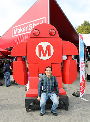 Just because we moved out of NYC doesn’t mean that we would miss one of our favorite events of the year: World Maker Faire! How do we explain Maker Faire? It’s an exhibition, festival, and celebration of technology, crafts, engineering, robotics, and everything DIY. It’s a gathering of inventors, tinkerers, scientists, artists, builders – all of whom are makers in their own domain. Held at the New York Hall of Science, the World Maker Faire is the largest of the international series; October 1-2, 2016 was the 7th annual event.
This year, we were thrilled to explore Maker Faire with Jon, Lily, and Jen! We chatted with creative minds of all ages and sizes and types. We learned about the latest machines, gadgets, and doodads. We heard about projects that others are pursuing and picked up ideas and tips for our own. We even made some things right then and there during the faire. Most of all, we had lots of fun!
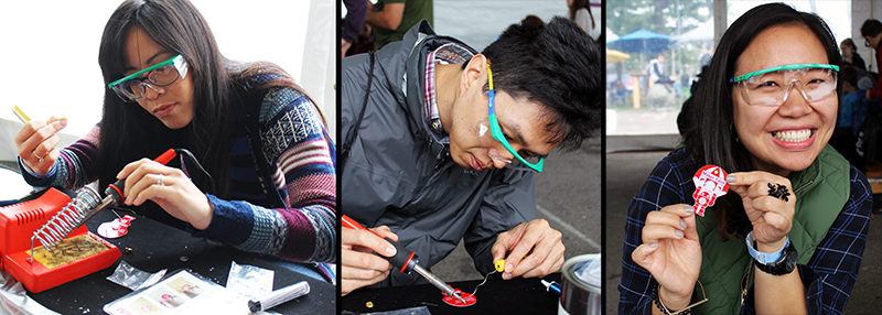
This is the first year we’ve participated in one of the most popular Maker Faire activities: learning to solder. Donned with Google safety glasses, we soldered a battery holder, pin, and LED to a printed circuit board in the shape of the Makey Robot. So easy and fun!
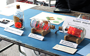 In the Maker Shed, we saw a vast array of innovative projects. One of our favorites was the circuits-in-a-bottle project by Kimio Kosaka. Incredibly, all the parts are soldered together inside the bottle. Unfortunately, this picture does not do this creative project justice! We were too busy marveling and asking questions. See more details on Kimio’s DIY video!
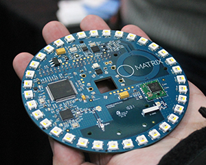
Maker projects spanned from fun at-home endeavors to commercial ventures. For example, we loved the MATRIX Creator, which is basically a Raspberry Pi add-on pre-built with a number of sensors and microcontrollers, powered by a proprietary (secret algorithm) operating system. Its capabilities are endless and clearly largely unexplored! Watch our video below to see one potential functionality: Face detection, tracking, and interpretation (also featured: our silly facial expressions :-P).
We tried our hand at single-pin lock picking. The instructions are much more easily explained than executed. Of our group, only Lily was successful! Here she is “supervising” Silas and Jon sweating away, hard at work.

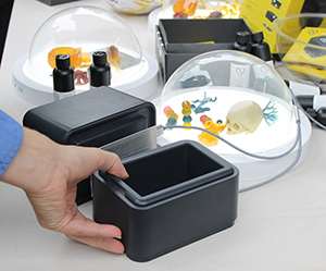 Years ago, at our first Maker Faire, we saw our first 3D printer. In a shockingly short amount of time, after decades of utility in industrial fabrication, these have now become mainstream. The MakerBot Replicator and even Formlabs Forms are old news and companies are now striving to distinguish themselves. Nowadays, you can 3D print plastics, metals, clay, rubber, even chocolates. We saw many examples of great efforts: printers which used plastic waste instead of filament or resin, others which printed and mixed different colored plastic, etc. We were most impressed by the ONO, the first-ever smartphone 3D printer which raised over $1 million on Kickstarter in just 5 days! A tray filled with DLP resin sits over the smartphone. This resin hardens with exposure to normal visible light. An app displays patterns on the screen to harden the resin while a moving platform pulls the hardened resin up so that the next layer can be printed. It should be available in the U.S. soon!
Check out this Knitting Printer, an awesome invention brought to us by Asbjørn Rørvik and Fredrik Fjellså from Norway! We were entranced by the process. So far it looks like its functionality is limited to making tubes – socks, scarves, and Dachshund sweaters… but who can have enough of those?! By the way, the component parts of these automated knitting machine were 3D printed, too!
Here are some other pictures of our highlights during the day!
1. Jon listening to knitting. Teresa Lamb wears a harness and arm-piece which translates the movements of knitting into sound.
2. Lily jamming out on a ukelele programmed with Arduino.
3. Kathy May operating Shaper Origin, the world’s first handheld CNC machine. It’s totally portable and self-guiding!
4. Silas examining water bears AKA tardigrades (indestructible micro-animals that can survive in outer space) under the microscope.
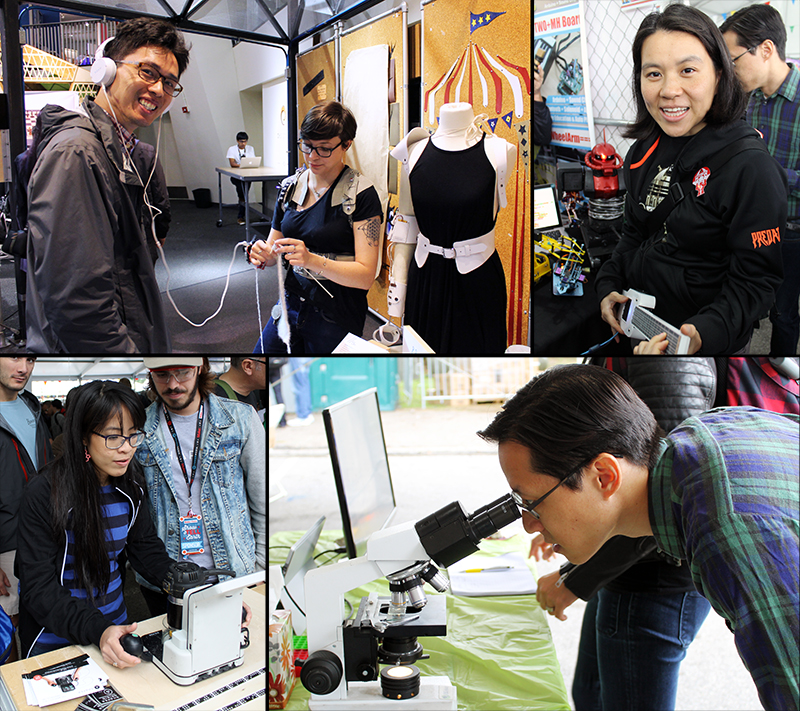
Check out our gallery for more Maker Faire pictures that we couldn’t fit into the body of this post!
[See image gallery at www.kathymayandsilas.com]Until next time,
Kathy May and Silas
The basic concept behind how the smart mirror works is that the one-way mirrored glass allows light coming from behind the glass to shine through but is reflective like a regular mirror wherever it is dark behind the glass. The tablet would display white letters on a black background so that the tablet itself would be as invisible as possible but the text would appear to be floating on the mirror.
We decided that the best combination of fast and cheap would be to apply mirrored window film to a picture frame and to use an old Android tablet for the display. These are the materials that we used:
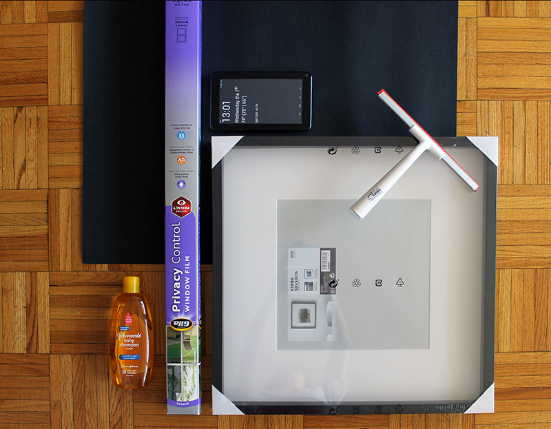
- Picture frame. You should choose a glass frame with a depth sufficient to contain your tablet and cord. We used a black IKEA RIBBA frame, 19.75” square (50cm square), $14.99.
- Mirrored window film. We decided on Gila privacy film, which we purchased on Amazon for $26. For other brands, variable opacities are available. One roll is plenty to make many mirrors.
- Baby shampoo and spray bottle. This is for the solution you will use in the application of film to the glass.
- Squeegee. We bought ours at IKEA with the frame for $1.99.
- Black posterboard. The backing which will accentuate the reflection of your mirror.
- Utility knife. To trim your film.
- Tablet. We used an old Android tablet which we no longer use. It’s an Azpen tablet which we bought at Micro Center years ago for about $30.
- Mirror app. Two apps that have been made available through Google Play by their authors are Wall Mirror and Home Mirror. Another app that is not on the app store but can be installed directly is Speculum.
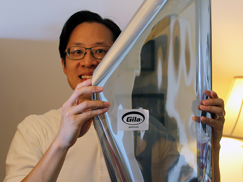
An alternative to using mirrored film on glass to create your mirror is to use acrylic or glass that is one-way mirrored (also known as two-way mirrored), which would replace the glass in your picture frame. These can be bought locally if you have a shop nearby or ordered over the Internet for delivery. Either way, they can be cut to order. A disadvantage of acrylic, however, is warping which is especially evident in larger sheets. Both mirrored acrylic and glass are expensive; a sheet of mirrored acrylic for a project comparable to ours would be around $65. We decided to go with film on glass, which is significantly cheaper, especially since the glass comes with the frame. Disadvantages include the patience and attention to detail required to apply the film evenly without bubbles or bumps. If you already have experience applying window film to your house or car, it should be easy. Otherwise, be sure to watch a video to learn the technique so that you have good results.
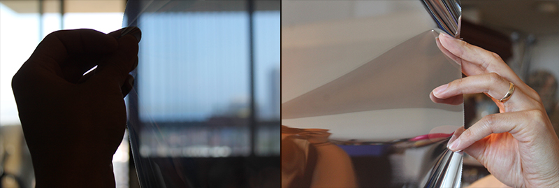
The mirrored window film is translucent when viewed from dark-to-light; it is opaque and reflective when viewed light-to-dark.
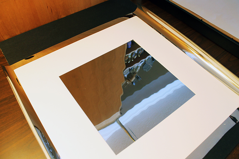
Cut the mirrored window film to the size of your frame, with at least an inch to spare on every side. An easy shortcut is to put the glass (or matting, if you have it) onto the sheet as a quick guide. The film will be trimmed; your cuts do not have to be straight.
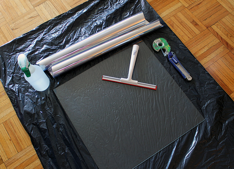
Get ready for the application of film to glass. There is water involved! We put a garbage bag down to contain the mess. Also, do this in as dust-free an environment as you can find. Even miniscule particles and fuzz will show between the film and glass.
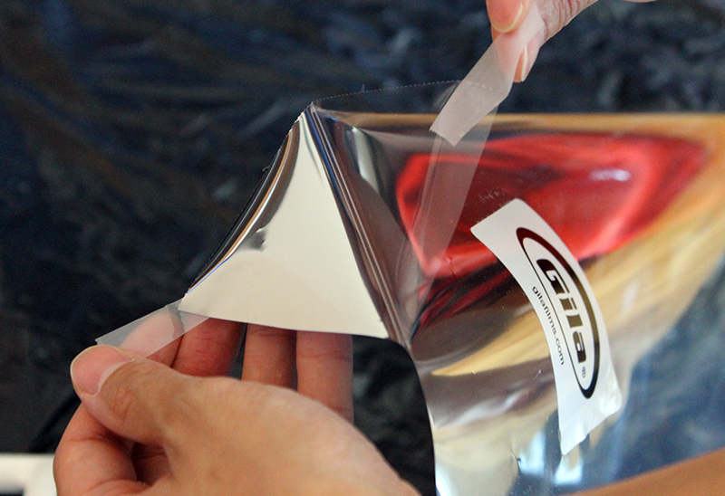
A great tip we learned that will certainly applicable to other projects is from Gila’s website: Apply scotch tape to the film side and the liner side for easy, quick separation without damaging the film.
Make your application solution in a spray bottle. Mix 1 quart of water with 1/2 cap of baby shampoo. Lay down your film with the side previously abutting the liner facing upwards. Lay down your glass alongside. Spray the solution onto both of these surfaces – be generous.
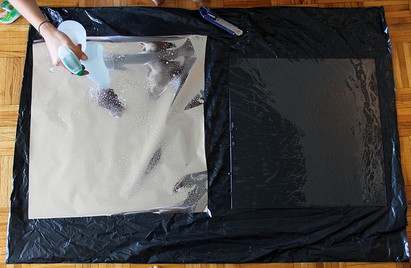
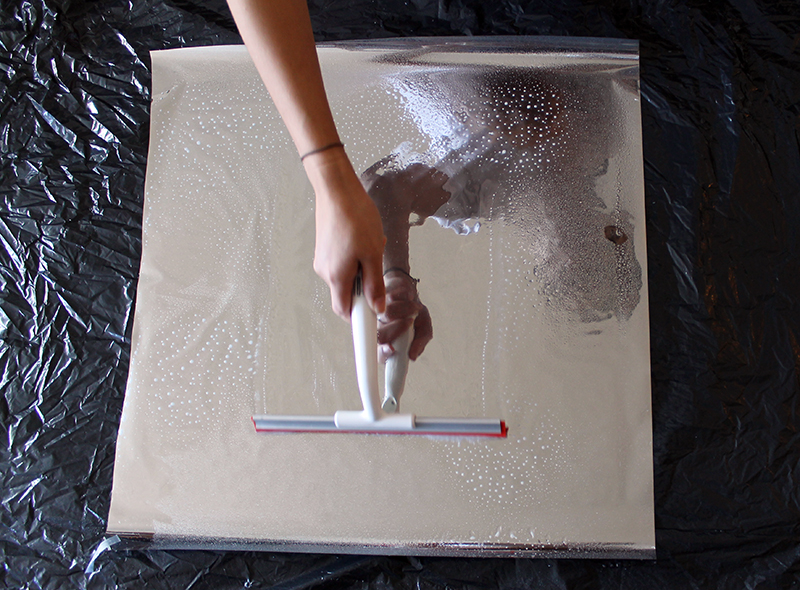
Apply film to the glass with the side of the film previously against the liner now against the glass. The two wet sides creates surface tension to hold the film to the glass. Next, spray the dry surface of the film – again, be generous. Use your squeegee to smooth out the film over the glass, removing wrinkles and bubbles as you see them. This works much better than trying to apply film dry! If you see any particles, you can lift the film to remove them and then continue.
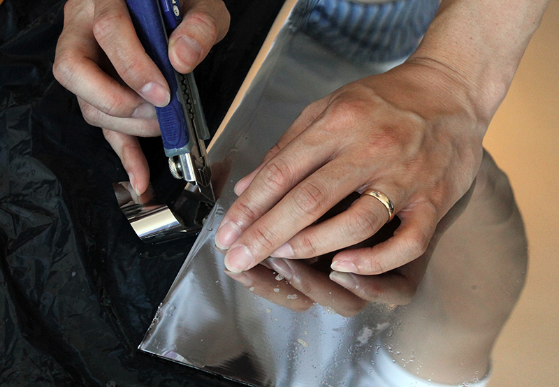
Trim the edges of the film by cutting along the perimeter of the glass with your utility knife. Use the edge of the glass itself as the guide. Try to be precise, because if you have excess film, it can lift up when you place the glass into the frame.
Next, in one corner of your black posterboard, cut a window that is the size of your tablet screen. The black against the mirrored window film will emphasize its reflective quality. Then construct some cardboard pieces to support the tablet and keep it in place. An alternative would be to tape the tablet in place but that makes it difficult to remove the tablet to make changes. After you’ve done this, it’s time to assemble your mirror! Place your film-covered glass into the frame (glass will be the outside; film will be the inside). Next goes your black posterboard and then the tablet, face-down, followed by the cardboard support and the backing for the frame.

We cut a hole in the cardboard for the tablet’s AC adapter cord to run; we also cut a corner of the frame’s backing for the same reason.
There are various options for the information display. We decided to use an app called Wall Mirror that Nick Hall wrote for his own smart mirror. It is available through the Google Play store and has an easy-to-use configuration tool to customize the display. You can see in the photos that we are using the time, date, weather, birthday, and calendar modules. This needs to be set up before putting the tablet into the frame. Since we didn’t tape down the tablet, however, it is very easy to remove the table to make changes. Using a premade app is the quickest way to getting the smart mirror up and running, and it requires no coding. Alternatives to using a premade app might be to write a custom app or to use a website displayed in a full-screen browser. Alternatives to using a tablet might be to use a Raspberry Pi or other miniature computer with a monitor.
In fact, now that we have the basic smart mirror working, we plan to upgrade it and build a more customized version. In order to accommodate the functionality we have in mind, we will look into using a Raspberry Pi with a monitor. Some ideas that may possibly make it into the project include:
- More detailed calendar and weather information
- Motion or proximity detection to turn off the screen when nobody’s looking
- Face recognition using a camera, so that the display is customized depending on who’s in front of the mirror
- Voice commands, for example to show more detailed information or to perform Google/Alexa/Cortana searches
Stay tuned for more posts as we build the next version of our Magic Mirror! Please let us know if you have built something similar or if you have any suggestions for us!
Until next time,
Kathy May and Silas
PS. Here are some of the tablet smart mirror projects from which we drew inspiration:
]]>We had been hearing about the Arduino for a while since attending our first NYC World Maker Faire a few years ago, and we decided that this was a perfect project to make use of one. Basically, an Arduino is an inexpensive microcontroller that can be programmed like a very simple computer to check inputs such as buttons and sensors, run some logic, and drive outputs such as lights and motors. A thermostat system, for example, would use a temperature sensor as an input to decide whether the HVAC should be on or off, and a servo motor and an output to physically control the HVAC unit. The Arduino by itself has no Internet capability, but add-on components that add Ethernet or WiFi abilities can easily be attached.
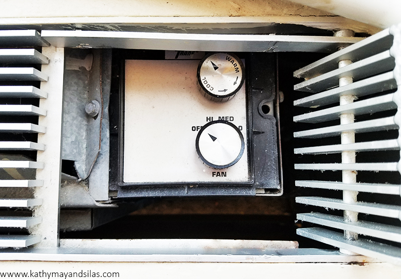
Our HVAC unit is controlled by a knob that turns the unit on or off, with several fan settings (high, medium, low). A second knob helps to control the amount of heating or cooling by cycling the heat transfer on and off. It’s not very efficient because the fan stays on at all times, and since you can’t set a temperature you basically have to guess how far to turn the knob to get the amount of heating or cooling you want. We wanted to build a system that would allow us to set a temperature like a thermostat and also to allow us to control system remotely (because who needs to go all the way across the room to turn the unit on and off?). Having it Internet-enabled would even allow us to turn the system on before reaching home, so that the apartment would already be warm when arriving home on those cold winter nights.
So far, our system has the following features:
- Measures and displays the current temperature in Celsius and Fahrenheit.
- Turns the HVAC unit on and off mechanically via the knob on the outside of the unit, in response to a direct on/off command or to maintain a set temperature.
- Reports the temperature and status to a web interface.
- Accepts commands through the web interface.
Here is a short video showing the system in action:
The system that we built has four principal components:
- Physical interface with the HVAC
- Arduino hardware not including the interface with the HVAC
- Arduino software (sketch)
- Web interface

In this post we will give an overview of each of these components. In future posts we hope to be able to go into each in a bit more detail.
1. Physical Interface with the HVAC
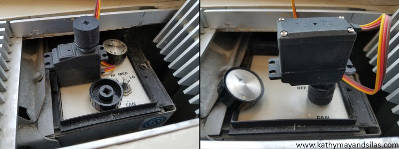
Instead of connecting to the wiring inside the control panel or to the power supply of the HVAC unit, we decided to build a mechanical interface to control the unit from the outside. This allows us to avoid working with high-voltage AC and allows the HVAC unit to be restored to its original condition easily. This mechanical interface obviously varies according to how the HVAC unit is designed, while the rest of the project is fairly independent of the design of the actual unit. Our HVAC unit is controlled by a knob that attaches to a shaft with a square cross-section. This is fortunate, because a servo motor can be used to turn the shaft directly on the same axis. A servo is a motor that can sense its own rotational position so that you can set it to turn to a specified position. This works well for us because we want to turn the shaft to the specified on and off positions.
 All that we need is a way to connect the servo to the shaft. Although we could have just glued the wheel horn directly to the knob, it would prevent us from restoring the HVAC to its original state. We thus 3D-printed a plastic knob with a square hole that we could permanently attach to the servo wheel horn. Since the geometry was not complex, we designed it quickly in Autodesk’s free 123D Design software. Since we don’t have a 3D printer (yet), we uploaded the design to Shapeways, which is a service that 3D-prints your design in whatever material you choose and ships it to you. The right image above shows the servo motor coupled to the HVAC control shaft.
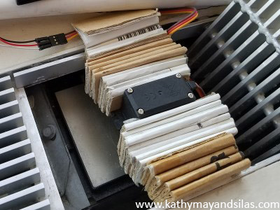
In order to hold the servo in position and provide counter-torque when the servo is turning, we used cardboard temporarily to hold it against the sides of the cutout of the HVAC enclosure. In the future we would build a more permanent and elegant mount for the servo but this works for now.
Here is a video of the servo in action:
2. Arduino Hardware
For our prototype, we used an Arduino Uno compatible board, which uses the ATmega328 controller chip at its core. We also used an Ethernet shield, which is an add-on board that provides access to wired Internet. We chose Ethernet because it is simpler to configure than WiFi and is more reliable, which is better for initial experimentation.

We used the following additional components for our project. Much of these came from online or Tinkersphere, a robot and electronics hobby shop in the Lower East Side of NYC.
- DHT11 temperature sensor (also measures humidity)
- Serial 8×8 LED matrix module with built-in MAX7219 driver chip, to display set and current temperatures
- Pushbutton to manually override the system to turn on or off
- RGB LED to indicate online status
- LED to indicate HVAC on/off status
- SPST switch to turn the temperature display on and off
- Breadboard, wires, resistors for the LEDs, DC barrel power jack for the AC adapter
The servo draws power directly from the AC adapter rather than the Arduino since the amount of current that the Arduino can supply is limited and the knob shaft requires a decent amount of torque to turn.
In order to get the temperature sensor further from the HVAC, we cut a 3.5 mm audio extension cable (which has 3 wires, matching the 3 connections that the DHT11 sensor needs) near the female end. The cut end of the short segment with the female jack connects directly to the board, and the cut end of the long segment with the male plug has the sensor soldered to it. Thus, in the future if we build an enclosure for the project, the temperature sensor can be plugged into the jack on the side of the enclosure like a pair of headphones plugs into a computer.
Although the system would have a web interface, we decided that it would also need a physical interface that shows the temperature and allows for manual control so that we wouldn’t have to go to the web all the time. We used a pushbutton to allow for override control to turn the HVAC on or off without thermostatic control. We used the 8×8 LED matrix to display the current and set temperatures in Celsius and Fahrenheit in a cycle that can be turned off with the switch.
3. Arduino Sketch
To program an Arduino to do what we want it to do, we write a program, or sketch, in a modified form of C/C++ using the free Arduino IDE (integrated development environment) on a computer. The sketch is then compiled and uploaded to the Arduino board via USB cable. It runs automatically when the board is powered up. Unlike a computer, there is no operating system or multitasking. The sketches are much simpler and smaller than your average computer program. On the popular Uno model of the Arduino, there is only 32 KB of program space and 2 KB of RAM! However, the power of the Arduino is in the ease with which the sketch communicates with the outside world through easy access to GPIO (general-purpose input and output) pins on the board.
Most home automation projects have very simple logic at their core, and so the Arduino has more than enough power to control this type of project. The logic behind a thermostat is very simple. If the room temperature is below the set temperature, turn the heat on. If the room temperature is above the set temperature plus a certain threshold, turn the heat off. And it would simply be the opposite for cooling.
Adding some bells and whistles such as communicating to a webserver does add to the complexity of the sketch, but the great thing about this kind of project is that you can add one piece of functionality at a time; it’s not necessary to plan out the whole project in advance.
Here is a basic schematic outline of our sketch. We hope to be able to go into a more detailed analysis in a future post. We used the following libraries: dht11 for the temperature sensor, Servo to control the servo, SPI and UIPEthernet for the Ethernet shield, SimpleTimer to run code at specified intervals, and LedControl for the LED matrix display.
The main thermostat function does the following: reconnect to the Internet if necessary, read the current temperature from the sensor, check the server for a new command, execute the thermostat logic (turn the HVAC system on or off depending on the temperature), send the current temperature and system status to the server, and display the current temperature on the LED matrix display.
The setup function connects to the Internet and sets up a timer to call the main thermostat function (above) each minute. The loop function checks the pushbutton that allows us to manually turn the unit on or off as well as the switch that turns the temperature display on the LED matrix on and off.
4. Web Interface
We want to be able to control and monitor the system using the web. This allows us to set the thermostat or simply turn the HVAC on or off without having to get up and walk all the way to the unit. It also allows us to start heating the apartment before reaching home!
The Internet-enabled Arduino can either be set up as a server or a client. With the Arduino as a server, we would send HTTP GET or POST requests to it directly to control the system, and it would serve up the user interface to our browser as HTML. However, we decided to use the Arduino as a client, requesting commands and posting its status to a hosted web service. Thus, the web server is an intermediary between our browser and the Arduino. This design has the advantages of not having to set up a static IP address for the Arduino, providing greater functionality (since the webserver has much more computing power than the Arduino itself), and allowing us to work on the user interface updates without having to remove and reprogram the Arduino.
Currently we have the Arduino set up to report the current temperature and system status (on or off, manual override or thermostat control) to the server once a minute. At the same time it will query the server to see if there is a new command. A simple web page provides an interface that we can access from any computer or smartphone, allowing us to see the temperature and status, as well as to change the set temperature or override it on or off.
Future Directions
There are some features that we have in mind that we are working on implementing in the future:
- Improving the web interface including designing a smartphone app
- Moving from the Arduino Uno to an Arduino Nano or other small version of the Arduino, and from breadboard to soldered perfboard
- Building a more permanent mount for the servo and an enclosure for the electronics
- Adding the ability to set programmed times with different temperatures – right now our schedules are not the same from one day to the next so this is not important to us
Even at this stage, we have been enjoying our first Arduino DIY home automation project! Being able to turn the heat on and off before reaching home makes living in the apartment much more comfortable, as does letting the Arduino maintain a steady temperature without having to get up and turn the unit on and off manually. We hope to go into more detail about each of these components sometime in the future, but hopefully this gives you a basic overview of our project. We hope that this gives you some inspiration and ideas for your own projects. Do you have any suggestions for our project? Please tell us about your Arduino and home automation projects in the comments!
Until next time,
Kathy May and Silas
[See image gallery at www.kathymayandsilas.com]
The IKEA Lack table is extremely popular. It is inexpensive, lightweight, and versatile. Its aesthetically simple shape is simultaneously attractive and neutral. Most importantly, it is HOLLOW which makes it a perfect hack for the installation of… well, anything you can imagine! For our first IKEA hack, we modified the Lack table with inset succulent gardens. Here’s what we used in the mod (we’ll mention the materials for the gardens later):
- IKEA Lack side table ($7.99-$9.99 depending on the color)
- Metal ruler (for measuring and as a straight edge)
- Pen
- Utility knife
- Two drawer organizer trays ($1 each at the dollar store)
The Lack tabletop is 55cm square. We planned for two separate insets at a diagonal 2in apart (our ruler is imperial units only). Rather than sitting directly in the tables, our gardens would be contained in these organizer trays that would allow us to remove them for watering and maintenance. The lip of the trays was advantageous, as it could sit upon the tabletop to hide any rough cuts. Here are Silas and his assistant measuring and marking.
[See image gallery at www.kathymayandsilas.com]After carefully preparing our cutting guides, we used our metal ruler as a straight edge and used our utility knife to cut the tabletop. We were patient in making repeated slices, as opposed to a sawing motion, so that our lines would be as clean and smooth as possible. FYI, the tabletop is made of pressed cardboard and is about 5mm thick.
[See image gallery at www.kathymayandsilas.com]Even when all the cuts were made, we found it difficult to remove the cut square because it was so flush! To make it easier, we drilled through the square, then used the hole for leverage to lift it up.
[See image gallery at www.kathymayandsilas.com]As promised, the IKEA Lack table is hollow! You can see that it is supported by innards of mere cardboard in a honeycomb configuration. Honeycombs are a naturally strong and efficient structure that can impressively withstand a great deal of compression. We easily cut and removed the cardboard from the table.
[See image gallery at www.kathymayandsilas.com]Turning our attention to the succulent garden insets: Our gardens would rest in a table without holes for drainage, so we wanted to create an environment that balanced natural drainage and moisture retention. Fortunately, succulents are hardy and forgiving. They do not require much water or soil. We gathered:
- Two organizer trays as above
- River gravel
- Sphagnum moss
- Potting soil
- Aquarium gravel
- An assortment of cacti and succulents
First layer was gravel; second layer was moss; and third layer was soil.
[See image gallery at www.kathymayandsilas.com]We selected a few of our intriguing succulents for display in our Lack gardens. One arrangement had a larger centerpiece with smaller plants surrounding; the other was a more natural arrangement of four plants. (Note: If you can help with identification, we would appreciate your comments below!) Finally, Kathy May dropped our tray gardens into the tabletop. They fit perfectly!
[See image gallery at www.kathymayandsilas.com]For top dressing, we used a medium-sized aquarium gravel. The greens of the succulents would be a visual pop in the clean, white background.
[See image gallery at www.kathymayandsilas.com]We threw together a couple of terrariums inspired from some we had seen at Mahoney’s Garden Center to sit on the opposite diagonals from the inset gardens. We used glass candle bowls that we found at the dollar store. Here is our final product!
[See image gallery at www.kathymayandsilas.com] [See image gallery at www.kathymayandsilas.com]The best thing about using the organizer trays is that we can change our minds! We can mix, match, and exchange the contents of the insets. We could do other types of sunken gardens like herbs or flowers (maybe with a built-in drainage system on the underside of the table). We could even inset decorative elements, like a miniature Zen garden.
[See image gallery at www.kathymayandsilas.com]Thanks so much for hearing about our DIY project! We have other IKEA Lack tables and we look forward to modifying – stay tuned to see what we do next. Do you have any ideas for future IKEA hacks we should try? Please share your thoughts with us in the comments below!
Until next time,
Kathy May and Silas
